


The Ultimate Thermal Guide for Qi2.2 25W Integration
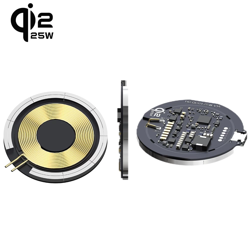
The Qi2 25W High-Power Era: A Deep Dive into the Top 3 Thermal Integration Solutions for Product Design
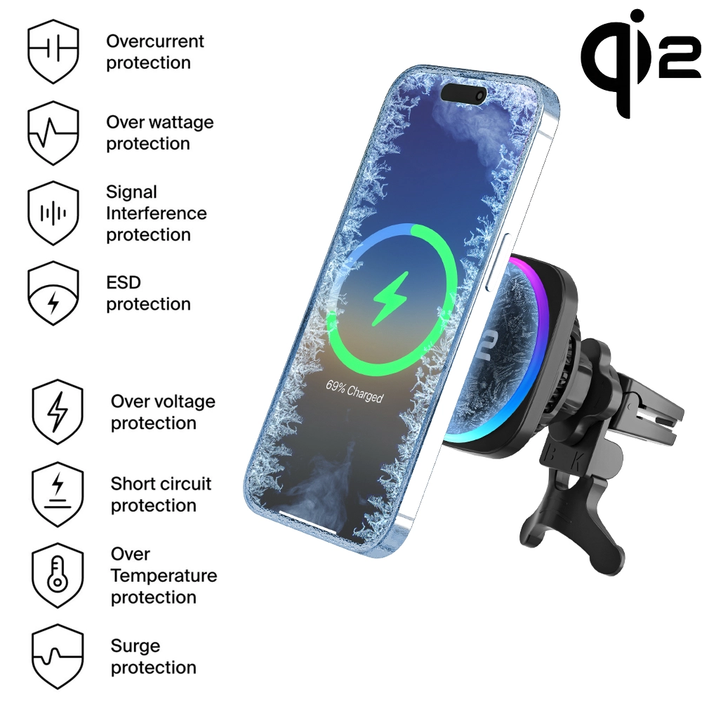
In the era of Qi2 25W high-power wireless charging, the heat generated by the PCBA has surged to more than 2.5 times that of traditional 15W solutions. Under the constraint of fixed PCBA designs, the thermal management at the product integration stage directly determines whether a device can pass Qi2.2 certification and whether it will trigger Over-Temperature Protection (OTP), leading to intermittent charging.
Currently, there are three dominant thermal solutions for 25W modules in the market. Below is a professional technical analysis of their advantages, disadvantages, and ideal applications.
1. Solution A: Active Fan Cooling
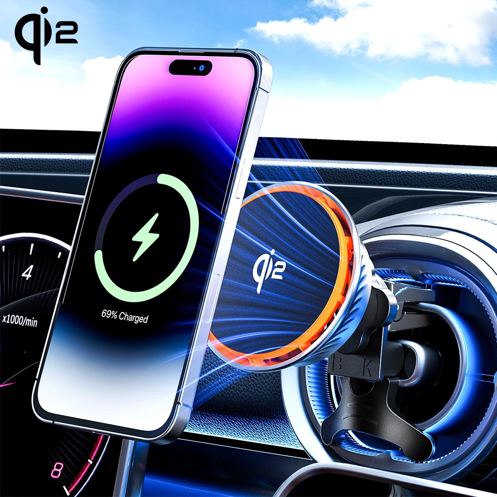
This is the preferred solution for top-tier accessory brands (such as Belkin and ESR) in their 25W desktop and car chargers.
Technical Principle: A micro-silent fan (usually an axial fan) is embedded within the housing. Through a precision-engineered air duct, cool air is forced across the surface of the coil and PCBA to carry away heat, which is then exhausted through ventilation ports.
Core Advantages:
Maximum Efficiency: Capable of reducing the temperature of both the smartphone and the charging module by approximately 5°C – 8°C.
Sustained Peak Power: It is currently the only solution that allows a phone to maintain a full 25W charge for over 30 minutes without thermal throttling.
Customization Constraints:
Form Factor: Requires extra thickness to accommodate air ducts; not suitable for ultra-thin designs.
Noise & Lifespan: Requires high-quality hydraulic bearing fans to minimize noise, and air ducts may accumulate dust over long-term use.
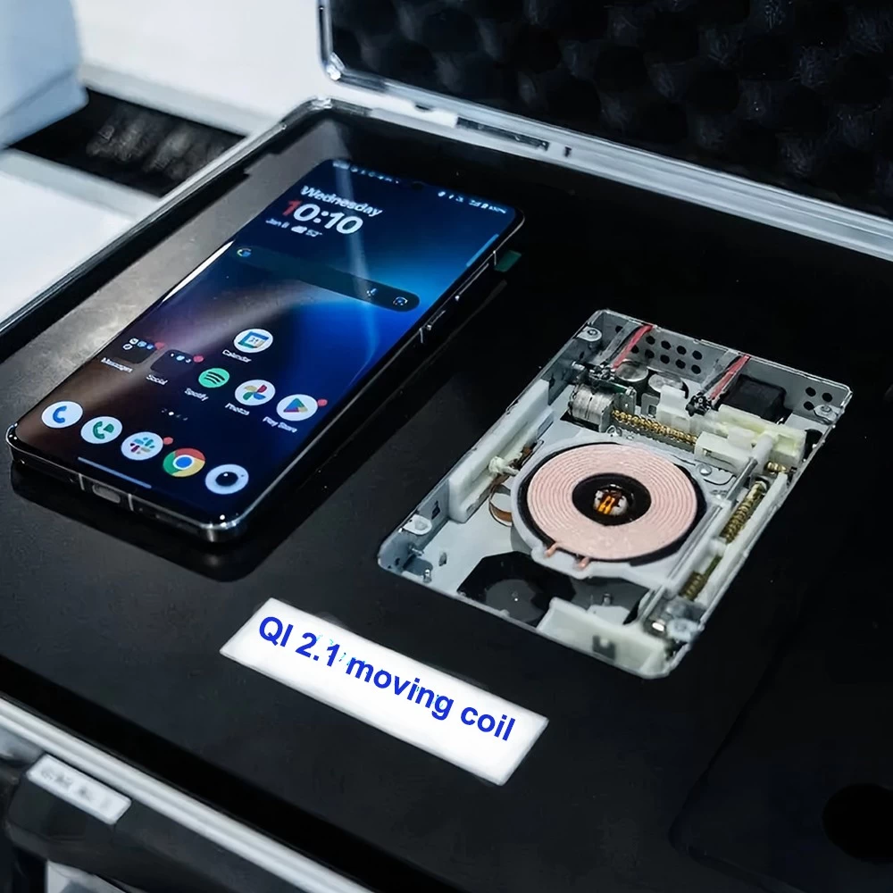
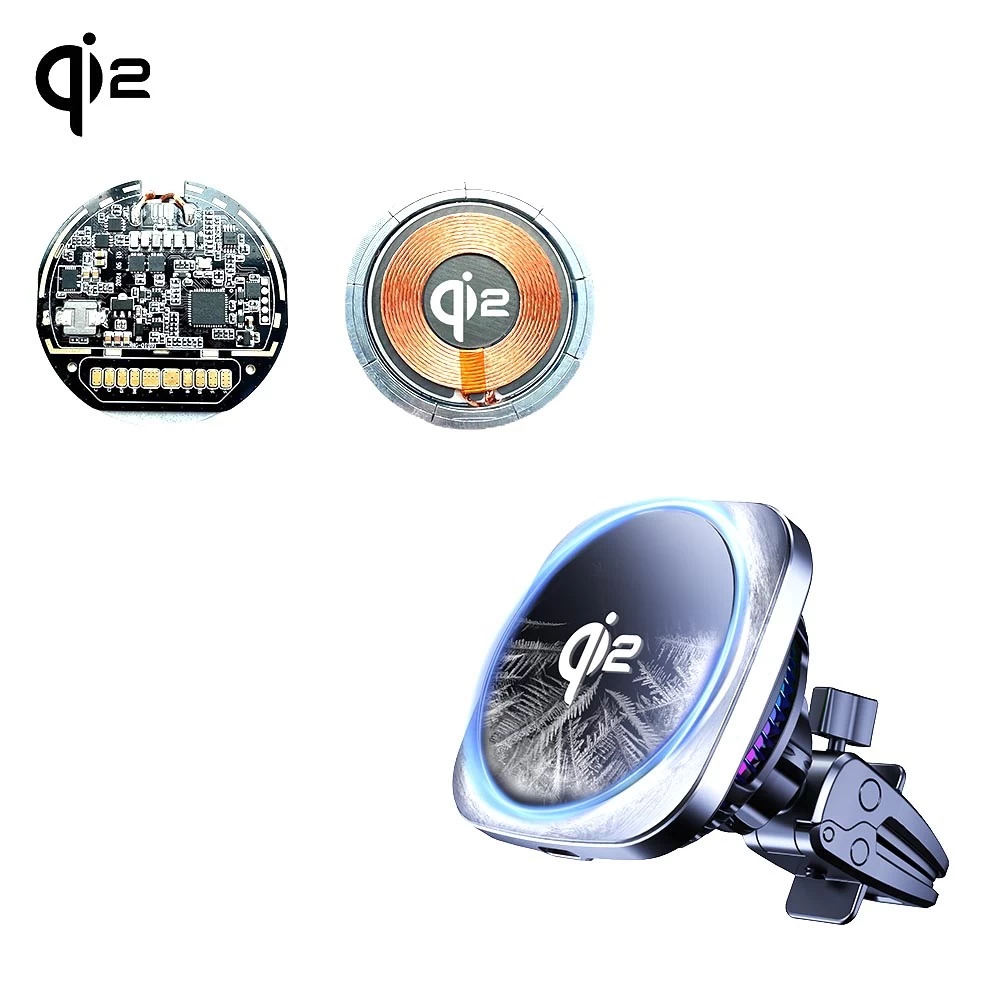
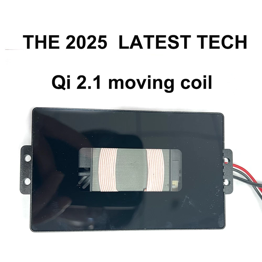
2. Solution B: Separated Structure Design (Coil & PCB Decoupling)
This is a "dimensionality reduction" strategy that solves heat accumulation through physical spatial separation.
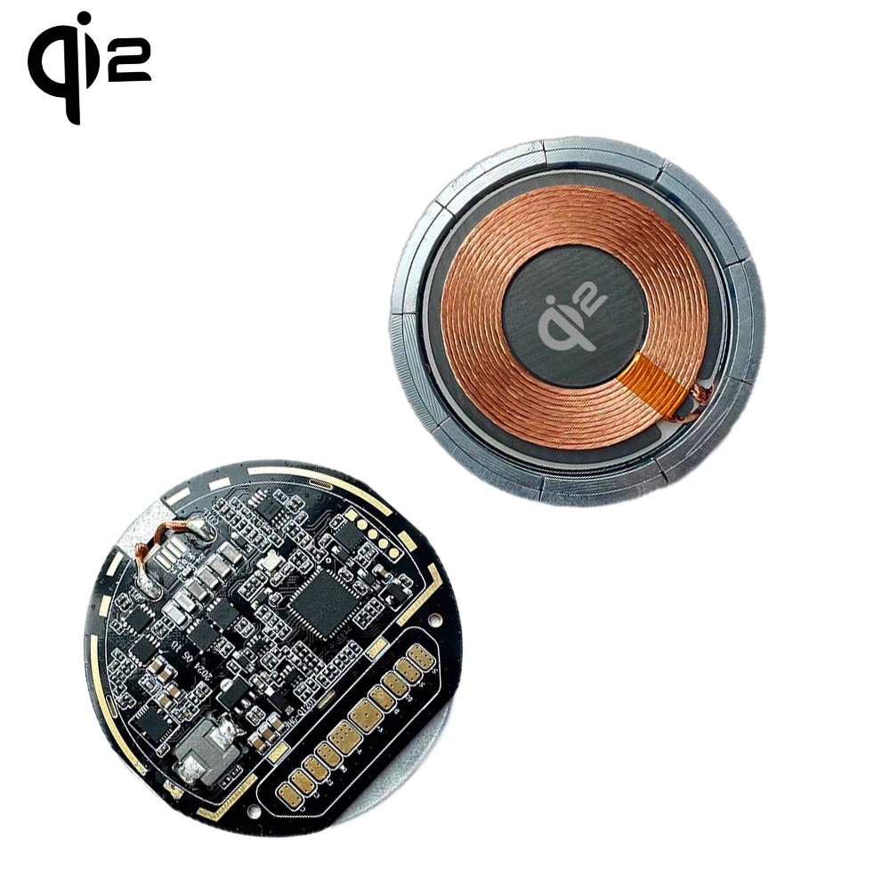
Technical Principle: The two primary heat sources—the Transmitter Coil and the Driver PCBA—are decoupled. They are connected via a Flexible Printed Circuit (FPC) or shielded cabling. Usually, the coil resides at the magnetic contact surface, while the PCBA is located in the base or mid-cable (similar to "puck-style" chargers).
Core Advantages:
Thermal Decoupling: Prevents the heat from the PCBA from transferring to the coil, significantly lowering the perceived temperature on the back of the smartphone.
Extreme Slimness: The charging head (contact end) can be made incredibly thin since it contains only the coil and magnets without electronic components.
Customization Constraints:
Line Loss: Increased distance between the coil and driver board can lead to higher impedance; improper handling may decrease transmission efficiency.
EMI Challenges: The longer high-frequency current path requires more rigorous Electromagnetic Interference (EMI) shielding.
3. Solution C: Thermal Material Integration (Potting & Gel Injection)
This is the most mature solution for industrial-grade customizations, such as automotive center consoles and furniture-embedded chargers.
Technical Principle: High-performance Thermal Pads or Thermal Potting Compounds are injected into the gaps between the PCBA, magnetic shield, and the product housing.
Core Advantages:
Full Sealing & Durability: Potting compounds often provide waterproof, dustproof, and shock-resistant properties, making them ideal for outdoor or automotive environments.
Passive Cooling Ceiling: By using compounds with high thermal conductivity (typically >3.0 W/m·K), heat is rapidly conducted to the metal housing or a large-area heat sink for uniform dissipation.
Customization Constraints:
Irreversibility: Once the potting compound cures, the product is nearly impossible to repair.
Weight Increase: Potting significantly increases the overall weight of the final product.